


Pervious Pavement Design
Hydrological Design Considerations
Design | Hydrological | Structural
![]() Hydrological Design of Pervious Concrete: a description of the fundamental hydrologic behavior of pervious concrete pavement systems and a demonstration of the basic design methodologies appropriate for a variety of sites and circumstances. The limitations of these methodologies will also be briefly discussed.
Hydrological Design of Pervious Concrete: a description of the fundamental hydrologic behavior of pervious concrete pavement systems and a demonstration of the basic design methodologies appropriate for a variety of sites and circumstances. The limitations of these methodologies will also be briefly discussed.
 The design of a pervious concrete pavement must consider many factors. The three primary considerations are the amount of rainfall expected, pavement characteristics, and underlying soil properties. However, the controlling hydrological factor in designing a pervious concrete system is the intensity of surface runoff that can be tolerated. The amount of runoff is less than the total rainfall because a portion of the rain is captured in small depressions in the ground (depression storage), some infiltrates into the soil, and some is intercepted by the ground cover. Runoff is also a function of the soil properties, particularly the rate of infiltration—sandy, dry soils will take in water rapidly, while tight clays may absorb virtually no water during the time of interest for mitigating storm runoff. Additionally, runoff is affected by the nature of the storm itself; different-sized storms will result in different amounts of runoff, so the selection of an appropriate storm design is important. This page will briefly discuss these topics.
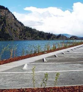
In many situations, pervious concrete simply replaces an impervious surface. In other cases, the pervious concrete pavement system must be designed to handle much more rainfall than will fall on the pavement itself. These two applications may be termed “passive” and “active” runoff mitigation, respectively. A passive mitigation system can capture much, if not all, of the “first flush,” but is not intended to offset excess runoff from adjacent impervious surfaces. An active mitigation system is designed to maintain runoff at a site at specific levels. Pervious concrete used in an active mitigation system must treat runoff from other features on-site as well, including buildings, areas paved with conventional impervious concrete, and buffer zones, which may or may not be planted. When using an active mitigation system, curb, gutter, site drainage, and ground cover should ensure that flow of water into a pervious pavement system does not bring in sediment and soil that might result in clogging the system. One feasibility study found that by using pervious concrete for a parking lot roughly the size of a football field, approximately 9 acres (3.6 hectares) of an urbanized area would act hydrologically as if it were grass.
Rainfall
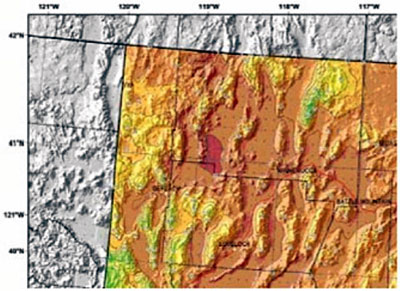 Figure 6. Isopluvials of 2 -year, 24-hour precipitation in tenths of an inch, for a portion of Nevada. Maps such as these are useful in determining hydrological design requirements for pervious concrete based on the amount of precipitation expected.
An appropriate rainfall event must be used to design pervious concrete elements. Two important considerations are the rainfall amount for a given duration and the distribution of that rainfall over the time period specified. Estimates for these values may be found in TR-55 and NOAA Atlas 2 or Atlas 14 maps (see Figure 6). For example, in one location in the mid-Atlantic region, 3.6 inches (9 cm) of rain is expected to fall in a 24-hour period, once every two years, on average. At that same location, the maximum rainfall anticipated in a two-hour duration every two years is under 2 inches (5 cm).
Selection of the appropriate return period is important because that establishes the quantity of rainfall which must be considered in the design. The term “two-year” storm means that a storm of that size is anticipated to occur only once in two years. The two-year storm is sometimes used for design of pervious concrete paving structures, although local design requirements may differ.
Pavement Hydrological Design
When designing pervious concrete stormwater management systems, two conditions must be considered: permeability and storage capacity. Excess surface runoff—caused by either excessively low permeability or inadequate storage capacity—must be prevented.
Permeability
In general, the concrete permeability limitation is not a critical design criteria. Consider a passive pervious concrete pavement system overlying a well-draining soil. Designers should ensure that permeability is sufficient to accommodate all rain falling on the surface of the pervious concrete. For example, with a permeability of 3.5 gal/ft²/min (140 L/m²/min), a rainfall in excess of 340 in/hr (0.24 cm/s) would be required before permeability becomes a limiting factor. The permeability of pervious concretes is not a practical controlling factor in design. However, the flow rate through the subgrade may be more restrictive (see discussion under “Subbase and Subgrade Soils” below).
Storage capacity
Storage capacity of a pervious concrete system is typically designed for specific rainfall events, which are dictated by local requirements. The total volume of rain is important, but the infiltration rate of the soil also must be considered.
The total storage capacity of the pervious concrete system includes the capacity of the pervious concrete pavement, the capacity of any subbase used, and the amount of water which leaves the system by infiltration into the underlying soil. The theoretical storage capacity of the pervious concrete is its effective porosity: that portion of the pervious concrete which can be filled with rain in service. If the pervious concrete has 15% effective porosity, then every 1 inch (25 mm) of pavement depth can hold 0.15 inches (4 mm) of rain. For example, a 4-inch (100-mm) thick pavement with 15% effective porosity on top of an impervious clay could hold up to 0.6 inches (15 mm) of rain before contributing to excess rainfall runoff.
Another important source of storage is the subbase. Compacted clean stone (#67 stone, for example) used as a subbase has a design porosity of 40%; a conventional aggregate subbase, with a higher fines content, will have a lower porosity (about 20%). From the example above, if 4 inches (100 mm) of pervious concrete with 15% porosity was placed on 6 inches (150 mm) of clean stone, the nominal storage capacity would be 3.0 inches (75 mm) of rain:
(15%) 4 in. + (40%) 6 in. = 3.0 in.
The effect of the subbase on the storage capacity of the pervious concrete pavement system can be significant.
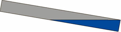
Figure 7. For sloped pavements, storage capacity calculations must consider the angle of the slope, if the infiltration rate of the subgrade is exceeded.
A critical assumption in this calculation is that the entire system is level. If the top of the slab is not level, and the infiltration rate of the subgrade has been exceeded, higher portions of the slab will not fill and additional rainfall may run to the lowest part of the slab. Once it is filled, the rain will run out of the pavement, limiting the beneficial effects of the pervious concrete. For example, if a 6-inch (150-mm) thick pavement has a 1% slope and is 100 ft (30 m) long, there is a 1-ft (300-mm) difference in elevation from the front to the back, and only 25% of the volume can be used to capture rainfall once the infiltration rate of the subgrade is exceeded (see Figure 7).
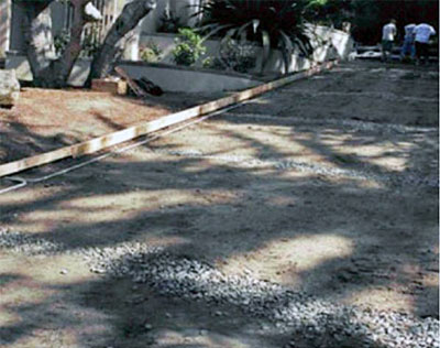
Figure 8. Preparation for a sloped installation. Crushed rock drains at intervals down the slope direct water away from the pavement and prevent water from flowing out of the pervious concrete (See also Figure 9).
These losses in useable volume because of slope can be significant, and indicate the sensitivity of the design to slope. When the surface is not level, the depth of the pavement and subbase must be designed to meet the desired runoff goals, or more complex options for handling water flow may be used. Pervious concrete pavements have been placed successfully on slopes of up to 16%. In these cases, trenches have been dug across the slope, lined with 6-mil visqueen, and filled with rock (see Figures 8 and 9). Pipes extending from the trenches carry water traveling down the paved slope
out to the adjacent hillside.
The high flow rates that can result from water flowing downslope may also wash out subgrade materials, weakening the pavement. Use of soil filter fabric is recommended in these cases.
Sub-base and Subgrade Soils
Infiltration into subgrade is important for both passive and active systems. Estimating the infiltration rate for design purposes is imprecise, and the actual process of soil infiltration is complex. A simple model is generally acceptable for these applications, and initial estimates for preliminary designs can be made with satisfactory accuracy using conservative estimates for infiltration rates. Guidance on the selection of an appropriate infiltration rate to use in design can be found in texts and Soil Surveys published by the Natural Resources Conservation Service (http://soils.usda.gov). TR-55 gives approximate values.
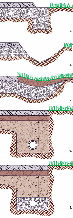
Figure 9. Example cross-sections of alternative drainage arrangements for use in impermeable soils.
(a) rock-filled trench under pavement; (b) rock trench along pavement edge; (c) V-trench; (d) rock-filled trench extending beyond pavement; (e) sand underdrain; and (f) sand underdrain with rock trench.
As a general rule, soils with a percolation rate of ½ in/hr (12 mm/hr) are suitable for subgrade under pervious pavements. A double-ring infiltrometer (ASTM D 3385) provides one means of determining the percolation rate. Clay soils and other impervious layers can hinder the performance of pervious pavements and may need to be modified to allow proper retention and percolation of precipitation. In some cases, the impermeable layers may need to be excavated and replaced.
If the soils are impermeable, a greater thickness of porous subbase must be placed above them. The actual depth must provide the additional retention volume required for each particular project site. Open-graded stone or gravel, open-graded portland cement subbase, and sand have all provided suitable subgrades to retain and store surface water runoff, reduce the effects of rapid storm runoffs, and reduce compressibility. For existing soils that are predominantly sandy and permeable, an open-graded subbase is generally not required unless it facilitates placing equipment. A sand and gravel subgrade is suitable for pervious concrete placement.
In very tight, poorly-draining soils, lower infiltration rates can be used for design. But designs in soils with a substantial silt and clay content—or a high water table—should be approached with some caution. It is important to recall that natural runoff is relatively high in areas with silty or clay soils, even with natural ground cover, and properly designed and constructed pervious concrete can provide a positive benefit in almost all situations. For design purposes, the total drawdown time (the time until 100% of the storage capacity has been recovered) should be as short as possible, and generally should not exceed five days.
Another option in areas with poorly draining soils is to install wells or drainage channels through the subgrade to more permeable layers, or to traditional retention areas. These are filled with narrowly-graded rock to create channels to allow stormwater to recharge groundwater (see Figure 9). In this case, more consideration needs to be given to water quality issues, such as water-borne contaminants.
Example
Consider sample calculations for a 3.6 inch (9 cm) (24-hr, two-year) design storm for a site with an active mitigation system composed of an automobile parking area 200x200 ft (61x61 m) of 6-inch (150-mm) thick pervious concrete with 12% effective porosity and 6 inches (150 mm) of clean stone (40% porosity) overlying a silty soil with an infiltration rate estimated to be 0.1 in/hr (2.5 mm/hr). The pervious concrete system is intended to capture the runoff from an adjacent building (24,000 ft² or 2300m², impervious) and contiguous park-like, grassed areas (50,000 ft² or 4600m²) caused by slope, sidewalks, and areas worn from use. In this example, the total runoff was estimated to be about ¾ inches (20 mm) over the entire site for a two-year, 24-hr storm. Without a pervious concrete stormwater management system in place, the predevelopment runoff would be expected to be 1.2 inches (30 mm) for this storm—about 50% more.